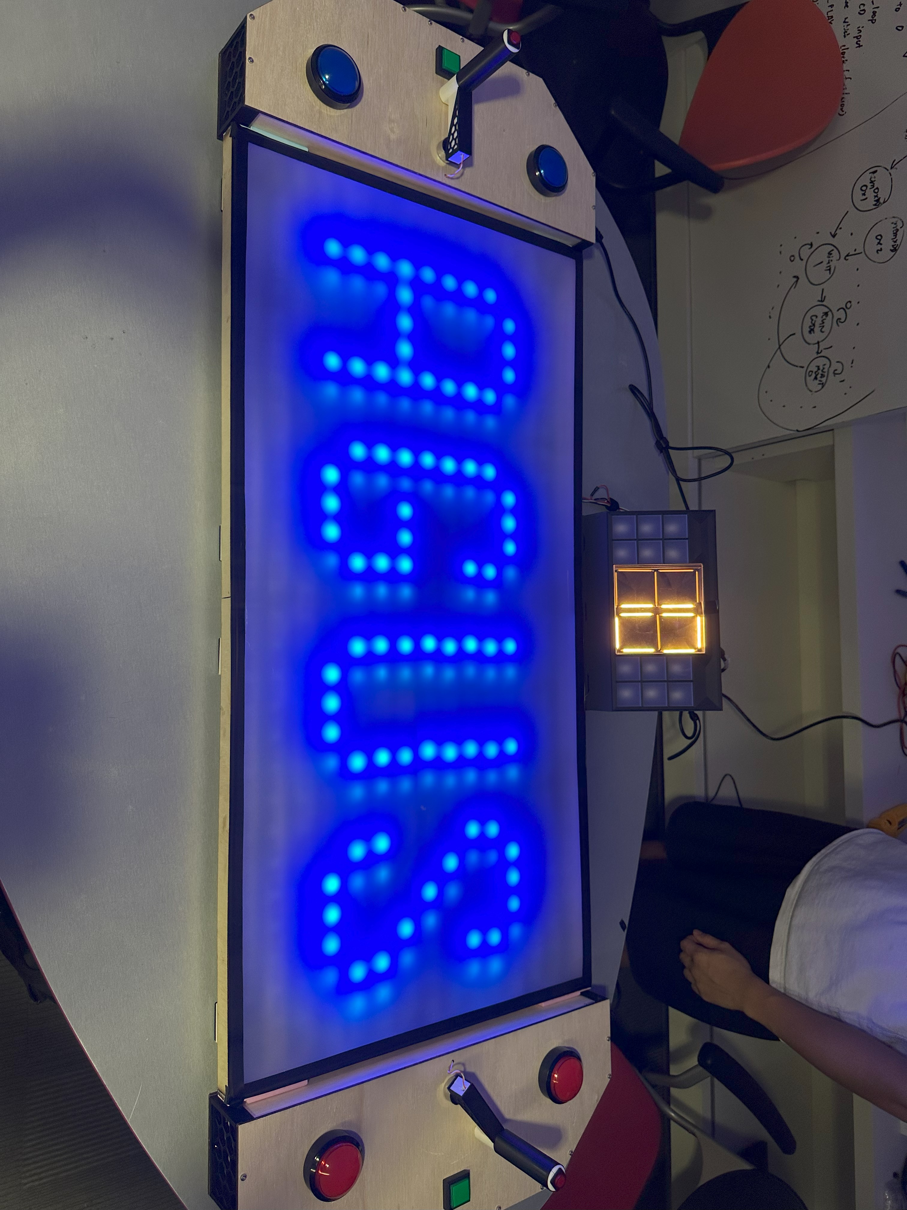
A.G.U.S.
50.002 Computational Structures
I worked with a team of 7 to develop A.G.U.S., an arcade-style game, from the gate level up using an Alchitry Au FPGA. The game features two-player gameplay similar to Pong, a large (in size, not in resolution) 30x15 WS2812-based RGB LED matrix screen and varying difficulty levels, and was implemented with a modified version of MIT’s Beta ISA.
Background
50.002 CompStructs isn’t strictly an EPD mod, but one I took out of interest (and to fulfil a minor in CompSci). The module is patterned after MIT’s 6.004, and goes through the basis of computing, from MOSFETs and gate-array logic up to programmable datapaths for computation. Part of this module involves a toy ISA developed by MIT, Beta, and its implementation on an Alchitry Au FPGA. As a final project, we were tasked with constructing an arcade-style game using the FPGA.
Using an ISA was optional, and most teams elected to use a simpler finite state machine (FSM) to implement their game. However, our team settled on the idea of a Pong-like game early on, and we made the decision to implement the full Beta ISA datapath in order to implement our game, due to what we saw as too much gameplay complexity to implement feasibly on a pure FSM.
Gameplay
A.G.U.S. is largely similar to Pong, with one key difference - instead of a ball spawning in the middle of the playfield, players “shoot” balls at their opponent using a turret-like aim handle, a “pre-arm” button, and a fire button, while defending against incoming balls using the left and right buttons. Players have limited “ammo” and lives (3 each), and the player that runs out of lives (or has the least lives when the timer runs down) wins.
Hardware
Every team was provided with an FPGA kit to develop their game on, which included a customized Br board with female pin headers. However, my team was concerned with reliability issues with the pin header connectors; the board had a lot of headers, and if we accidentally pulled out hardware connections, finding the right headers to connect our peripherals to would be a nightmare. As such, after we settled the specific hardware components we would use and the pinouts for each component, I made a dedicated connector board for the hardware we used.
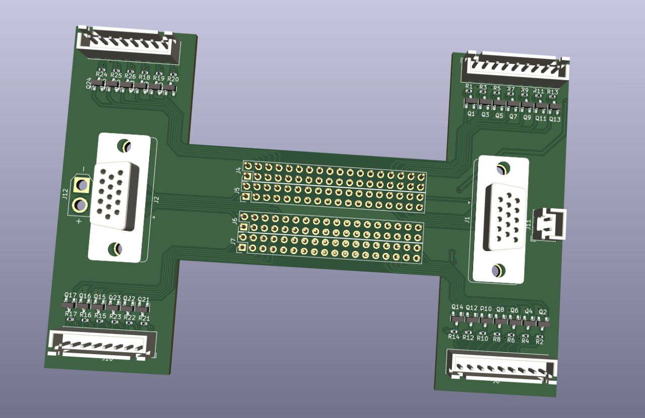
Alchitry doesn’t have specific board dimensions for the Br board available online, so I manually measured the positions of the 0.1” pin header grid on the Br board, then drew up a simple PCB that connects the signal pins on the Br board to a set of JST connectors for the timer 7-segment display, ammo and life indicators, and the player inputs. (We used VGA connectors for the player input because we thought it would be funny.)
I 3d-printed a test piece using a board model exported from KiCad to test-fit before ordering:
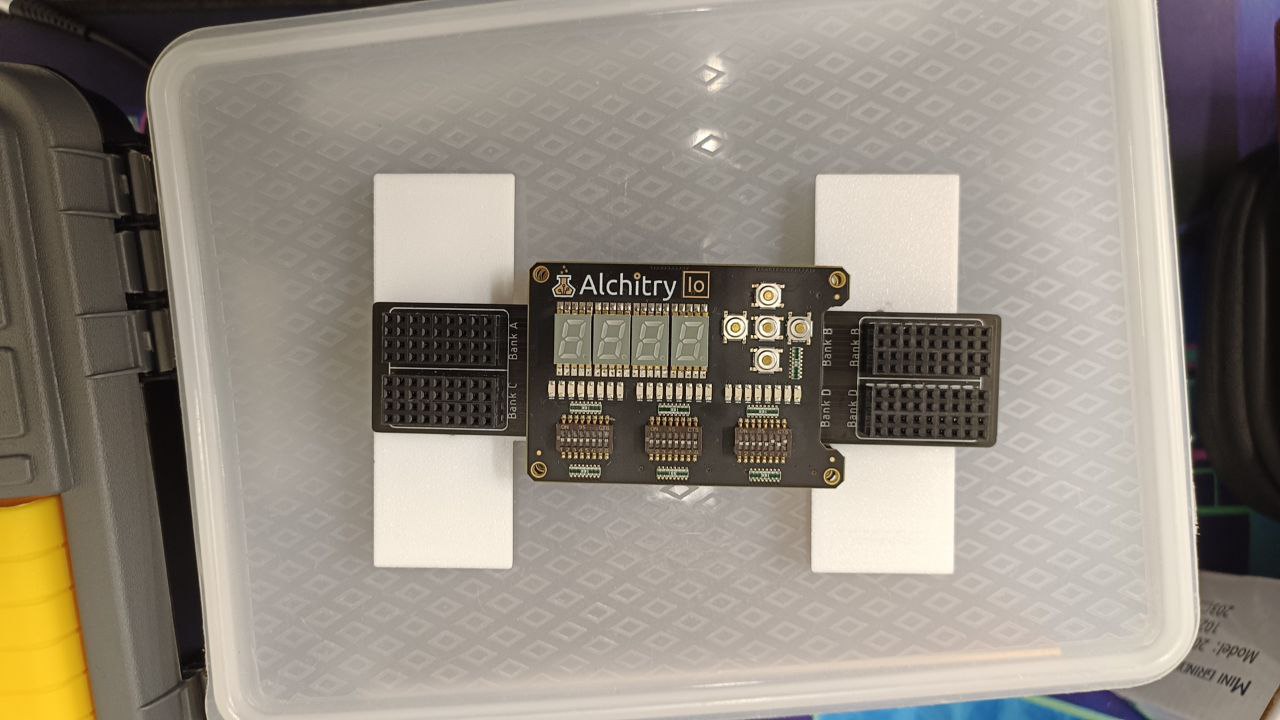
Also pictured: the original pin-header “wings” PCB distributed by the teaching team.
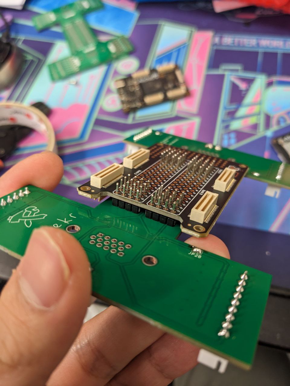
I ended up having to make changes to the wiring on the PCB, which you can see as grey jumpers here; the pins I thought were signal pins were not, in fact, signal pins. (Note to self: always double-check the pinout before assuming pin functionality.) Luckily, I included test points that made it easier to jerry-rig the PCB like this. While we didn’t have time to order another round of PCBs, this technique is something I’ll bear in mind for future projects.

Software
I designed the programmable hardware (“software”) of the project, while my teammates handled the specific implementation of the game itself in machine code. As such, I had to define an interface (an API, but not really) for their code to output the game state to the display.
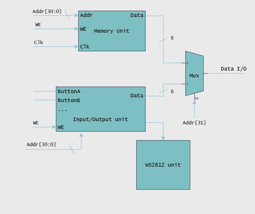
The architecture I came up with doesn’t add any new components to the Beta ISA datapath (including a bank of registers, memory units for instructions and data, an integer ALU for computation and a program counter), and instead uses a side-channel device to handle I/O. This device has an internal bank of memory mapped to one half of the working memory space, which is updated as inputs arrive from the button panels, and is used to draw pixels on the screen on every frameclock tick.
This architecture makes for reduced workload, as no new instructions or interrupt handlers need to be implemented to utilize the I/O unit; at least, that was the primary consideration, as my teammates and I had other committments during that period. We ran at a low enough tick rate that we didn’t run into any problems with clock collision between the side-channel unit and the main CPU; this probably won’t work at higher clock speeds.
The game itself runs on a tight loop, updating the velocities and positions of each ball by checking collision and player input, then making decisions about the game state based on the new positions of each ball, before passing this info back to the I/O unit to “render” on the display.
Conclusion
This was a whirlwind of a project, encompassing everything from hardware and PCB design, to low-level computing architecture and programming, all within the span of just over 4 weeks. While I definitely would’ve done some things differently from the start - planning for more instrumentation, for one - the knowledge and design techniques I’ve picked up will definitely be useful in the future.