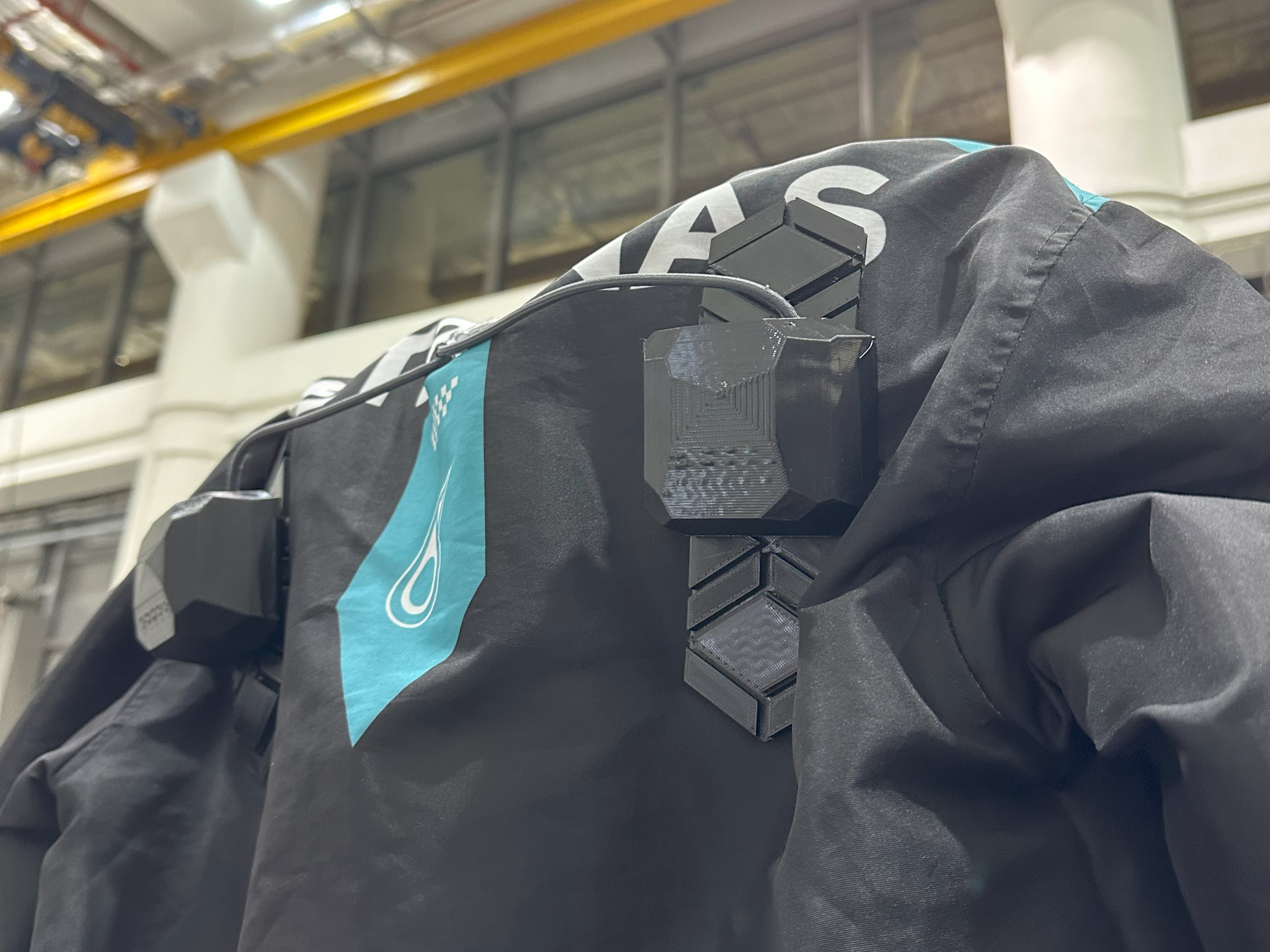
Sixth Sense
30.007 Engineering Design Innovation
Sixth Sense is a wearable vehicle detection system for motorcyclists. It detects unsafe vehicles that riders may not be able to detect, and lets the rider know about it through haptic and visual feedback. Sixth Sense works with a motorcyclist’s existing gear, and aims to bridge the gap between current state-of-the-art solutions, and riders without access to these solutions.
As the lead electronics designer in a group of 6, I architected the multi-microcontroller system that drives Sixth Sense, and spearheaded tight electronics integration with PCBAs. I also accelerated the group’s mechanical design process with advanced multi-material additive manufacturing techniques.
We initially embarked on this project as coursework, but we’re currently exploring further commercial development.
The Problem
Motorcyclists are involved in a disproportionately large number of traffic incidents. For example, locally in Singapore, motorcyclists make up about 15% of the vehicles on the road, yet account for more than 50% of all road fatalities. Two of our group members are motorcyclists, so this also has personal significance for us.
One of the major problems motorcyclists face, and one that we personally experienced when trying out a stationary motorbibke, was impeded road awareness. While experienced riders may have muscle memory, it’s hard for new, inexperienced riders to constantly check mirrors and blind spots, especially with the limited vision full-faced helmets present.
Current rider safety solutions on the market are either built into high-end motorbikes, or otherwise require third-party mounts. However, built-in solutions are usually expensive, and a user survey conducted towards the start of the project revealed that many motorcyclists don’t like mounting devices onto their motorbikes, whether it’s because of cost or potential damage to the bike, that they own multiple bikes or don’t own their bike at all, or pure aesthetic reasons. Current peripheral information systems on the market also suffer from ecosystem lock-in, as well as distracting, ineffective visual feedback. Research turned up haptic feedback as an untapped potential solution to the problem of providing auxiliary information to a rider without being too distracting.
As such, we set out to develop a wearable vehicle detection and notification system, utilizing haptic and visual feedback, that a rider could integrate into their usual riding habits with minimal extra expenses. Our prototype had to
- work with exiting typical riding gear,
- avoid mounted devices on the motorbike, and
- present minimally distracting yet recognizable warnings to the rider.
The Concept
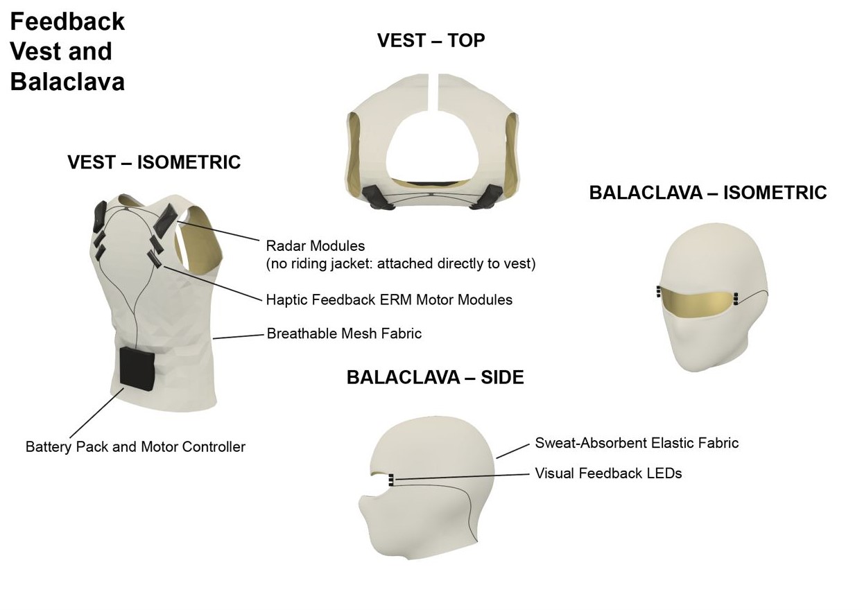
Our solution revolved around a vest that riders wear on the inside of their riding jacket. This vest places vibration motors around the rider’s shoulder area, as well as externally detachable radar modules that riders place on the outside of their riding jacket, which magnetically couple to the inner vest. The vest also comes with a balaclava with embedded LEDs around the viewport, which bounce light off the inside of a rider’s helmet to provide visual feedback.
In order to simplify wiring, we made the decision to use a multi-MCU architecture, in which every component of our system – vehicle detection, user feedback and battery management – is managed by a dedicated microcontroller. This was inspired partly by existing vehicle electronics systems, and partly by my hobby work on 3D printers, in which toolhead electronics are increasingly being handled by a dedicated toolhead microcontroller. This greatly reduced the amount of wiring required throughout the vest, reducing the likelihood of user movement causing a component to fail and generally reducing bulk.
We initially wanted to use a CAN bus as the communication link between the MCUs; we reasoned that we’d need to run power from a battery pack anyway, and a wireless protocol would introduce too much latency for our needs. However, through the prototyping process, we found that ESP-NOW had sufficiently low latency for our needs, and opens up future development pathways to make the system completely wireless.
Prototyping
Throughout the prototyping process, I focused primarily on the vehicle detection units, while the rest of my team focused on the haptic and visual feedback units, the battery pack, as well as the vest itself.
After some market research into automotive sensing, I settled on 60+GHz mmWave radar; radar seemed the most commonly used technology for medium- to long-range detection, and mmWave sensors are typically smaller than their longer-wavelength counterparts. More importantly, mmWave sensors are also available as antenna-on-package (AoP) chips, meaning I wouldn’t have to do any PCB antenna design, a task I wasn’t familiar with. We found a development module for one such AoP chip (Acconeer XM125), bought a few units and got to work.
First attempt
Our first attempt aimed to get the module working and to read some values. I didn’t want to build a PCB for the board immediately, so I started by soldering wires directly to the LGA pads on the board.
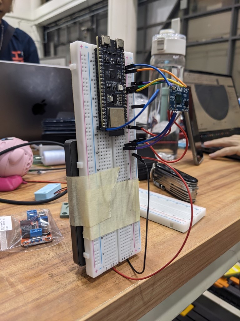
That’s an ESP32-S3 devkit on a breadboard with the radar module floating above it, with a mini power supply duct-taped to the other side of the board.
Using this setup (or similar), I validated the voltage supplies and connections required by the module, and wrote an I2C driver library for the Distance Detector reference application distributed by Acconeer. Part of that library is (a very naive implementation of) velocity calculations from measured distances.
The end goal was a nicely integrated PCB, which meant I need to figure out how to solder the module down onto the PCB. This was my first foray into reflow soldering.
Reflow
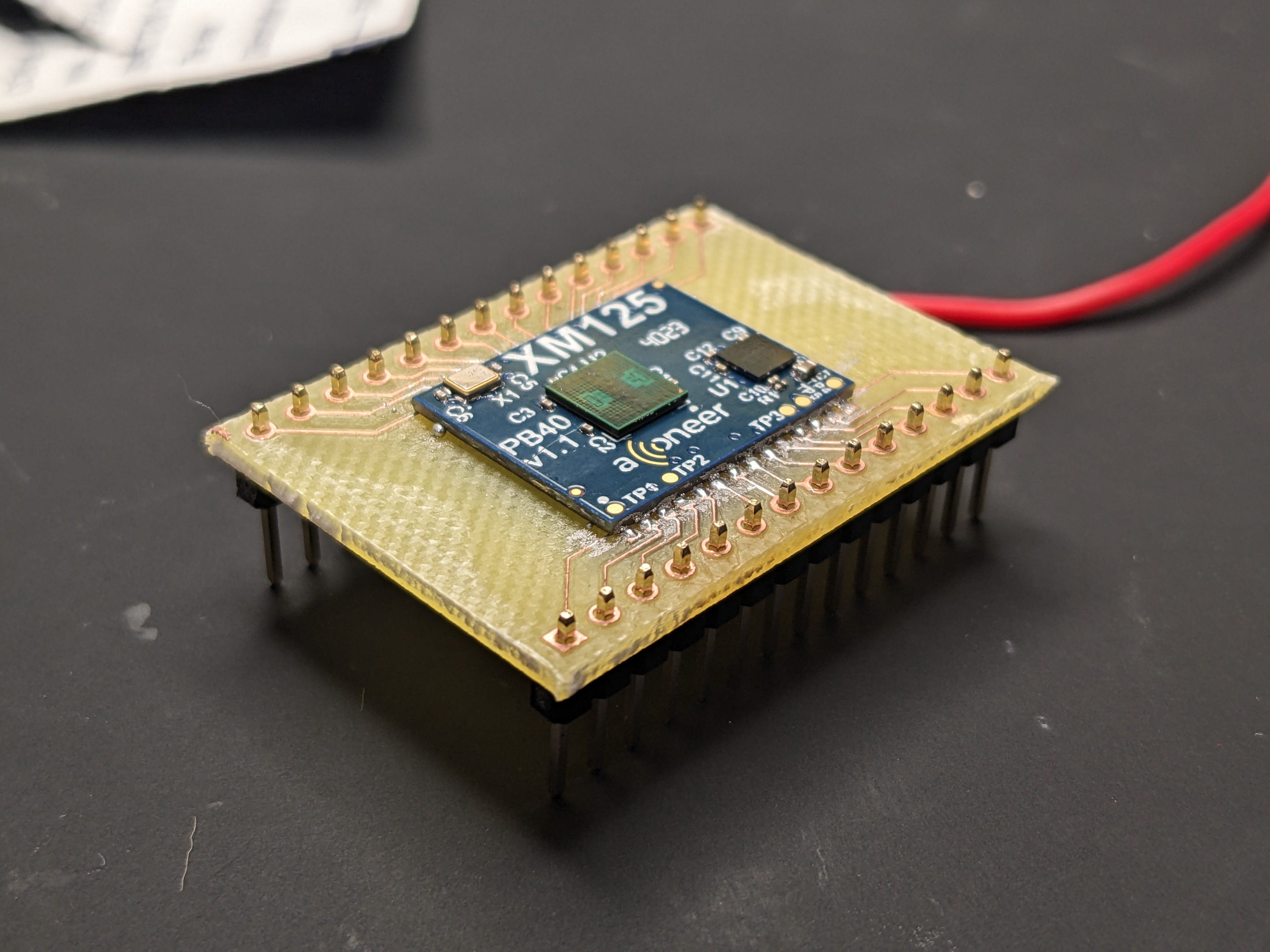
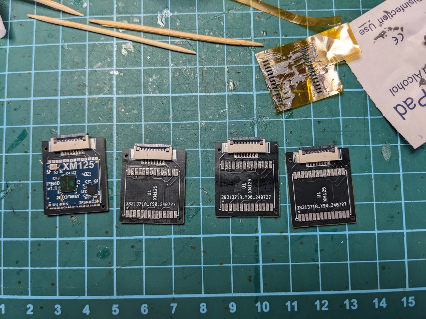
After drawing a footprint for the module’s LGA pads in KiCad, I used our FabLab’s PCB mill to cut a simple breakout.
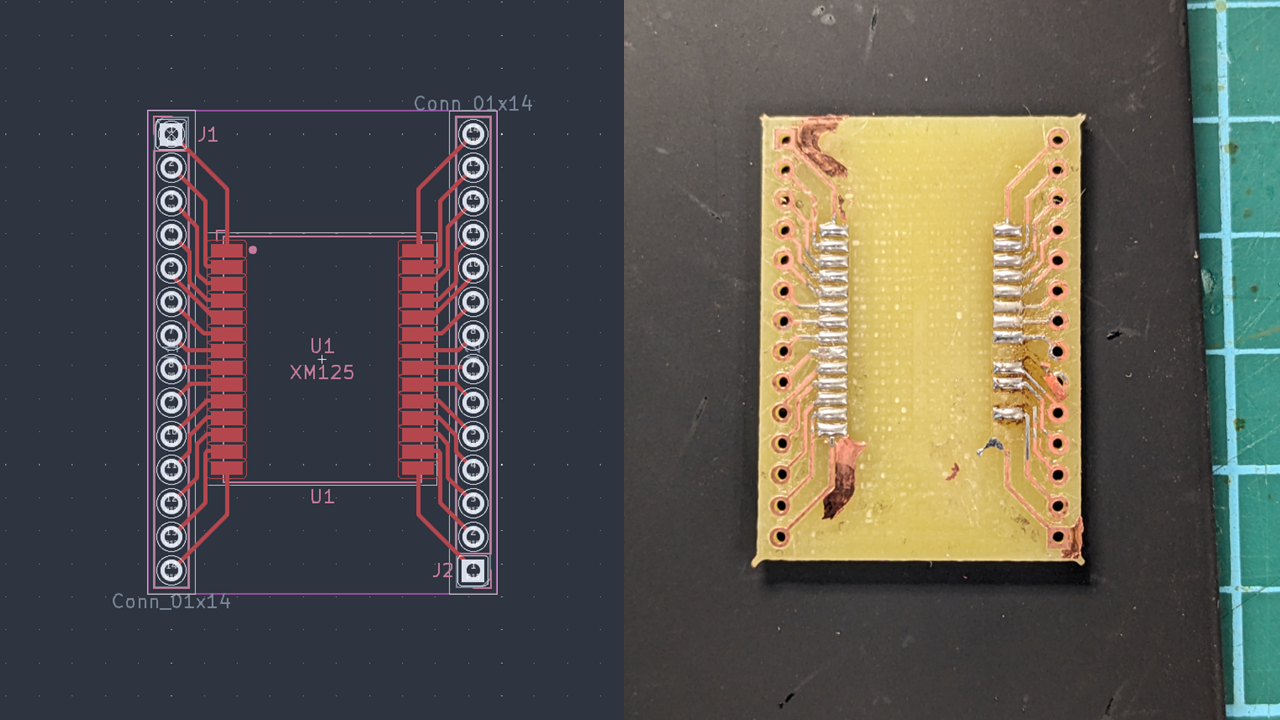
The PCB mill isn’t always super well calibrated, resulting in unremoved blobs of copper seen on the right. This is something we experienced throughout the project.
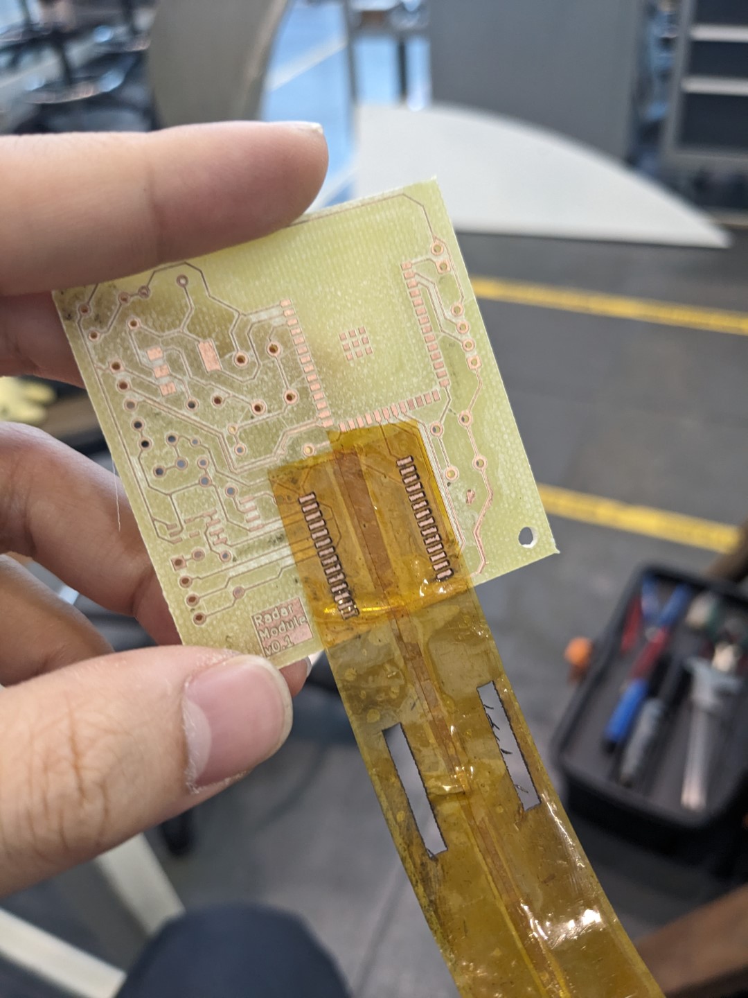
I first experimented with applying solder paste directly to the pads, which resulted in fairly inconsistent results; the blobs of paste would often overflow and bridge the pads. I then found out I could laser-cut stencils out of pieces of Kapton tape, which worked great in applying an even coating of paste.
Further integration
With the reflow process validated, the next test was to ditch the external power supply, and try to run everything off of a common voltage source – including the microcontroller.
The end goal was to integrate ESP32-S3 modules (the PCB modules with the integrated antenna) onto the board. To that end, I drew up a board implementing the ESP32-S3 module and radar, and cut it on the PCB mill.
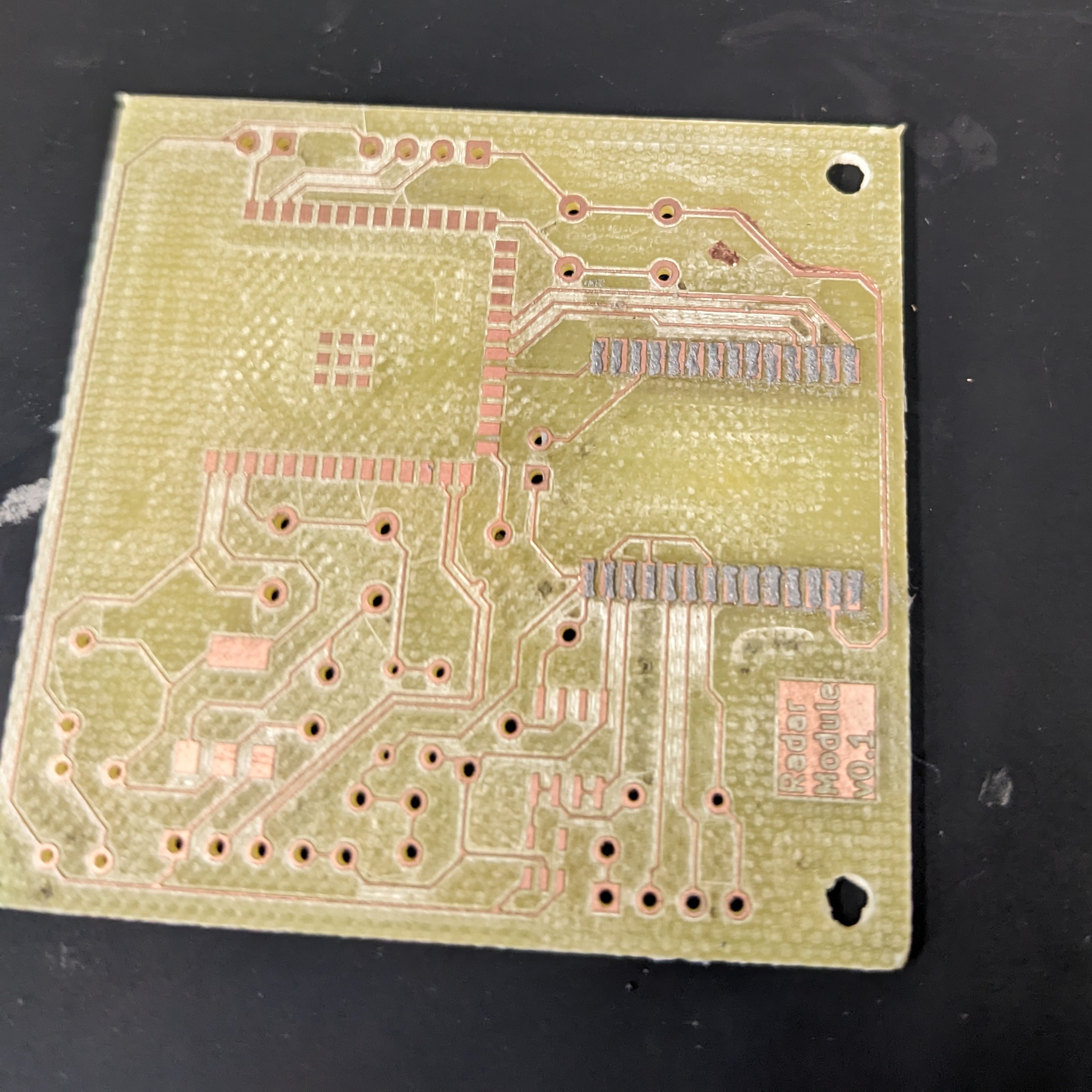
I then soldered the radar module onto the board with the kapton stencils, then hand-soldered the ESP32-S3 module, the two voltage regulators, and all its passives.
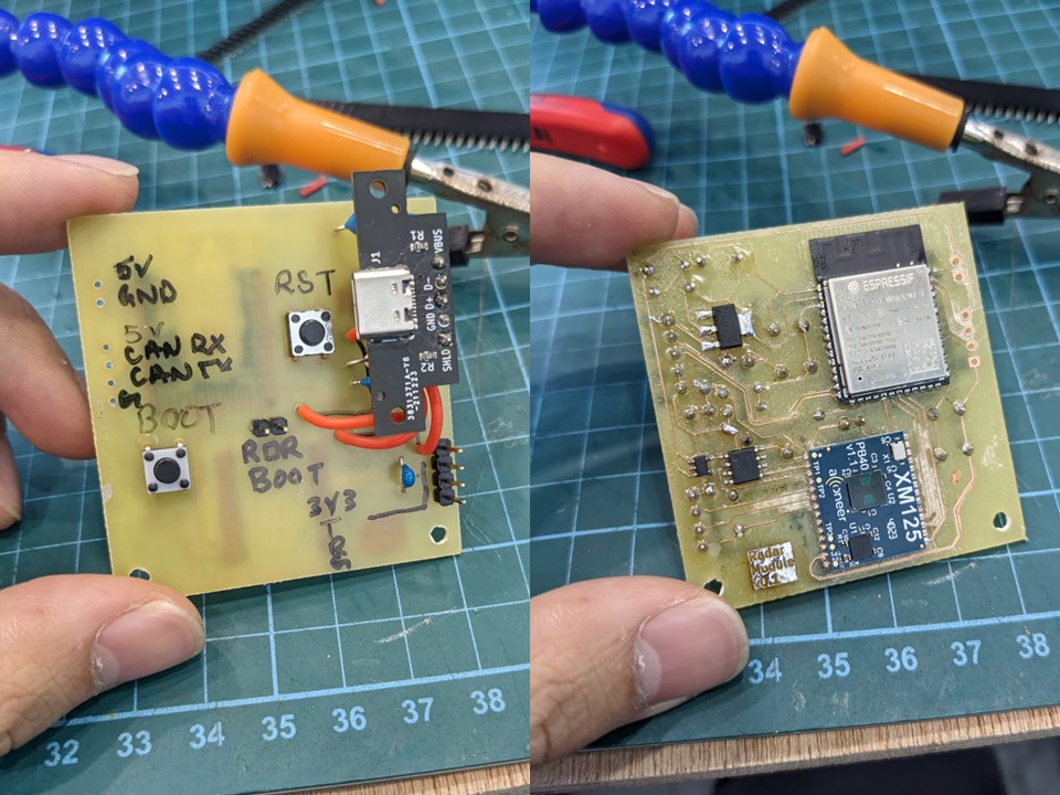
However, this didn’t end as well as we hoped; for one reason or another, the ESP32 wouldn’t connect to our PCs over USB, and eventually over the debug serial link as well. We didn’t have time to thoroughly debug this iteration, so I soldered the regulators onto breakout boards, verified the circuit on a breadboard, then transferred everything onto a soldered stripboard for further testing, using an ESP32 development board for the time being.
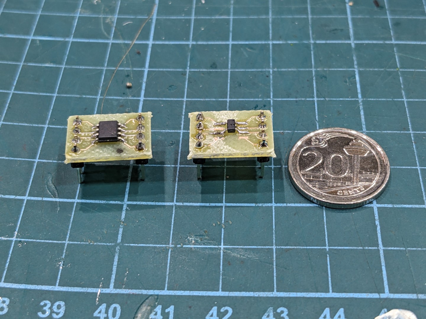 The bigger packages - SOT-223 and SOIC-8 - aren’t that hard to solder. SOT23-5, on the other hand…
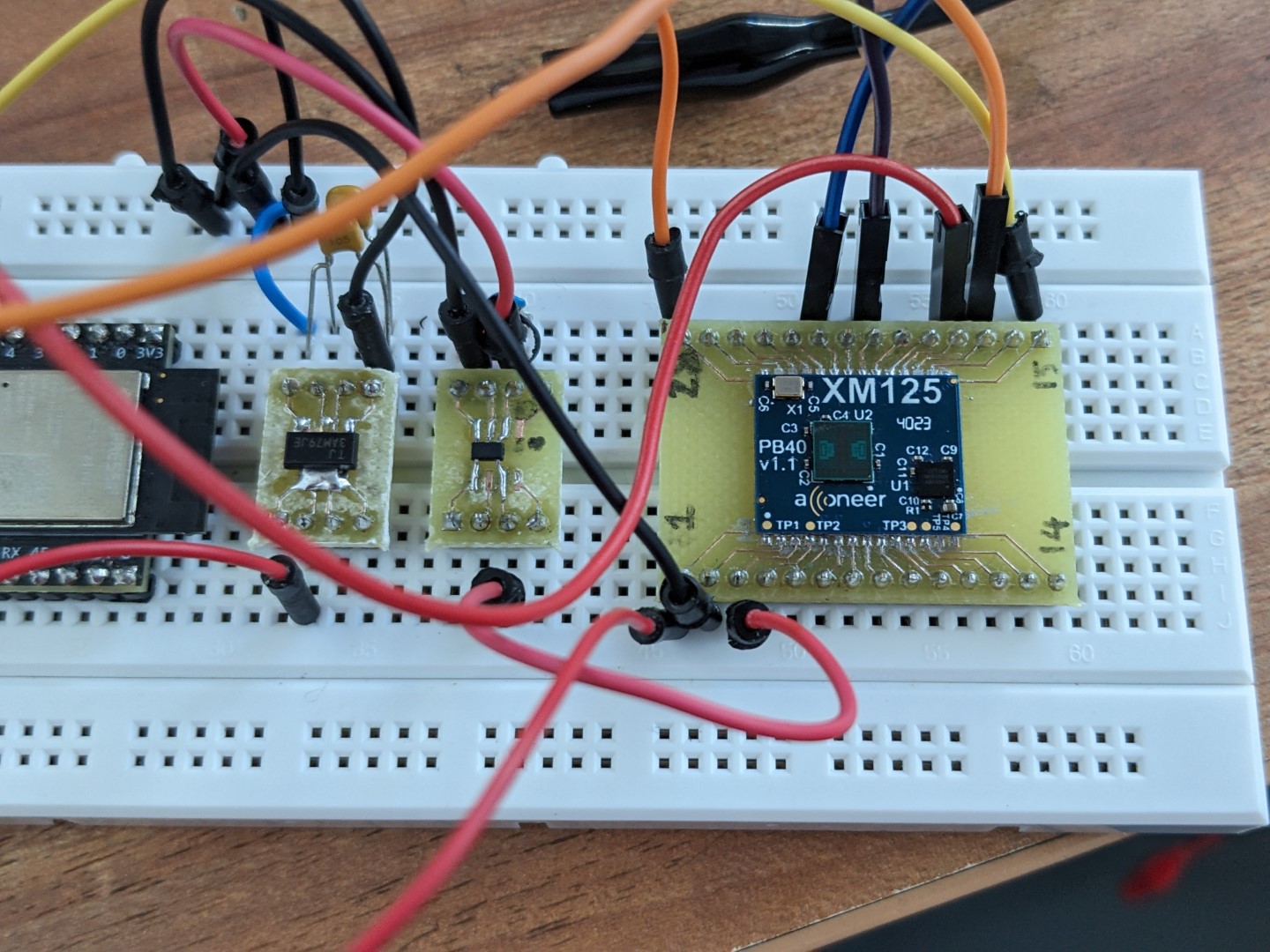 The breadboard turned out to induce a big enough voltage drop that the voltage supply for the radar modules fell out of tolerance. That was the main reason we moved to a stripboard.
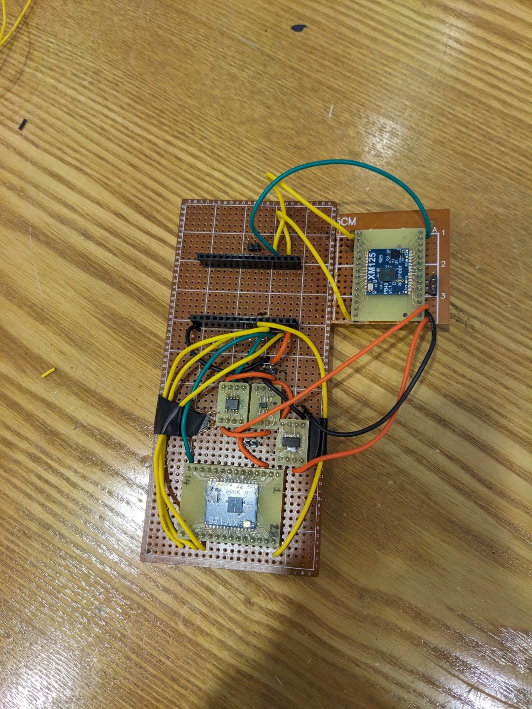 The two headers on top fit an EPS32 devkit.
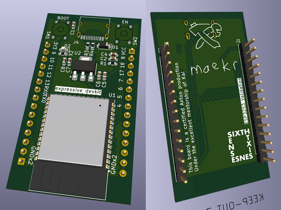
Simultaneously, I guided one of my groupmates, Anton, to validate our ESP32-S3 implementation by outsourcing board production of a sample implementation in the form factor of a DevKit, in order to eliminate our process as the source of error. This ended up working like a charm.
Final pass
With our schematics for each part of the vehicle detection unit validated, and with not a lot of time left on the schedule, we finally moved on to full integration.
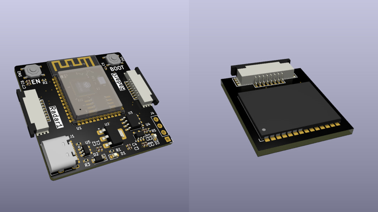
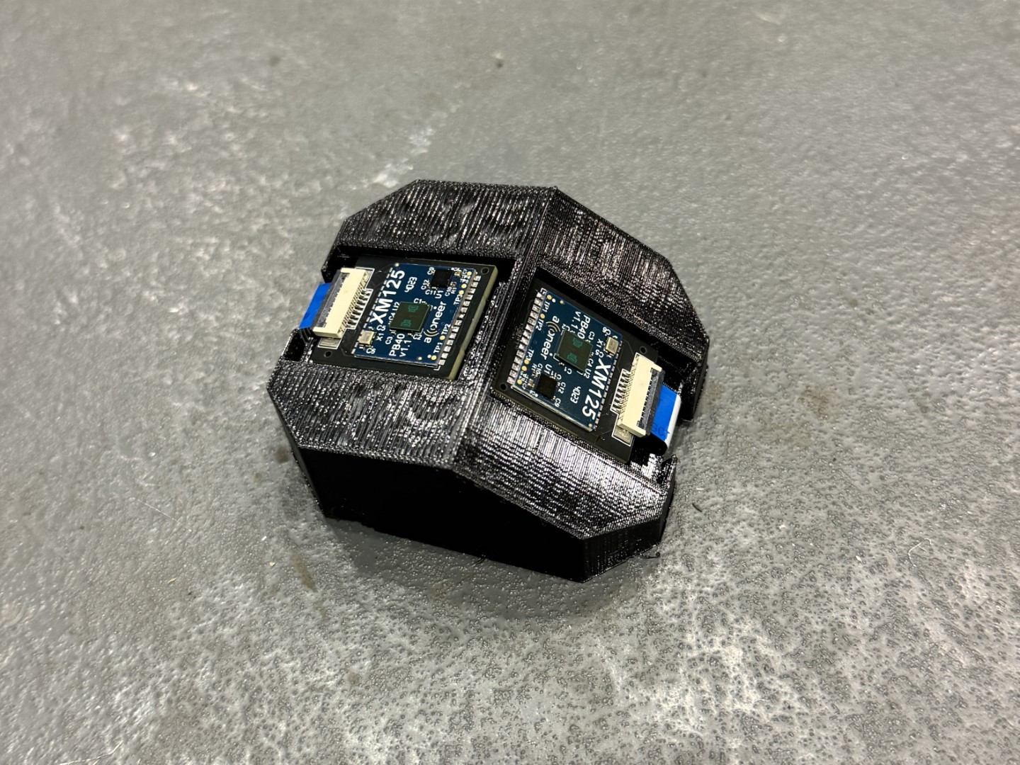
From testing we did with the stripboard prototype, we found that the field of view (FoV) on the radar sensor wasn’t as wide as we were looking for; as a stopgap solution, we wanted to use two radar modules, each pointing at a different angle, to fully cover the required detection range. Since we couldn’t achieve that with just one board, I designed a board that would take two radar modules, connected to the ESP32-S3 MCU with flexible flat cables (FFCs).
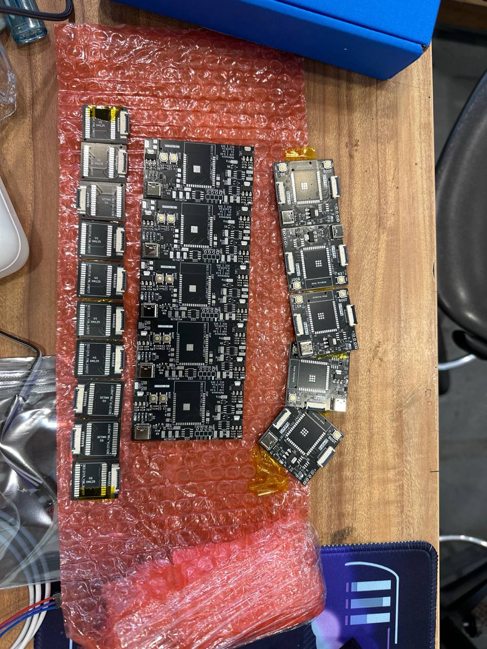 In the middle: Anton’s controller board for haptic feedback
This board was then fitted into the final housing, with 5V/GND out a hole in the housing.
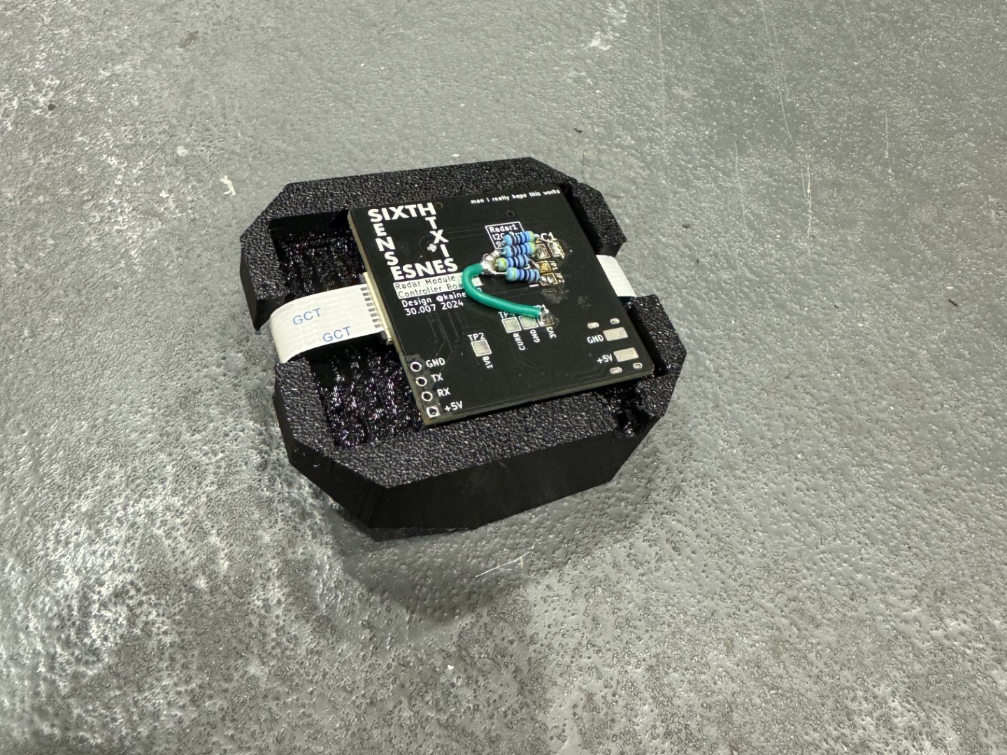 Of course I had to bodge it. Luckily, I included test pads for the connections I needed to rework.
3D printing
Concurrently with my work on electronics, I also brought my 3D printer’s multi-material capabilities up and running, enabling rapid prototyping for the housings.
One of our design goals was to minimise the hardness of objects worn by the user, to reduce the chance of injury during an accident. Flexible materials would also help with form fitting. As such, we used printed TPU for all our housings. However, if supports are required to print the model, these supports are typically quite difficult to remove, resulting in visual defects.
Multi-material printing can help with this; by printing the main model in one material and its supports in another, the support interface can be made fairly close, supporting the model fully and minimising the “droopy” lines commonly seen with overhangs. Because the support material (ideally) won’t fuse with the primary material, these supports can then be very easily removed.
My Voron Trident has an independent dual extruder (IDEX) setup, allowing dual material capabilities. Towards the end of the project, this was used heavily to print our enclosures. This capability opened up a lot of design options that may not necessarily have been available with traditional FDM processes.
Test model for dual extruder calibration
Test model for multi-material printing. Black is TPU, green is PLA. This model also included a hard PLA interior as a capability test.
We also took advantage of the FDM process to embed magnets in our components:
Testing (and failure)
Throughout this prototyping process, we took readings from the radar sensor to characterise how well it could detect vehicles, as well as the best parameters to pass to the Distance Detector reference application.

However, despite our best efforts, we couldn’t get reliable ranging measurements with the radar. Any configuration changes I made seemed to trade presence detection and detection rate for range accuracy and consistency. Part of this could definitely have been fixed in software; the reference application I was using seemed fairly limited and opaque in what I could configure, and there exists an interface for the actual underlying radar that we did not have time to explore. On the other hand, part of this is also likely the wrong choice of radar; shorter wavelengths result in greater precision but weaker radar returns, and we definitely did not need the mm-precision that mmWave offers. Given more time and resources, I would definitely choose to explore other sensing technologies, but within the timeframe of this prototype (and this course), we chose to stick with this particular sensor.
Conclusion
While the component I worked on ultimately did not work in time for the project showcase, this project has taught me a lot about the process of designing, integrating, assembling and testing electronics. From problem and feature scoping, to collaborating on ECAD and MCAD with my groupmates, to hand-soldering and reflow soldering assembly techniques, to bodging and reworking circuits for future revisions, I have picked up many, many skills in electronics design and assembly, as well as in project management and leadership.
Acknowledgments
I would like to thank my groupmates for their hard work and dedication throughout this project, without whom this project would never have gotten off the ground:
- Anton Karve
- Julian How
- Gwynne Ang
- Mak Weng Hui
- Chris Folk
… as well as our course instructors, Profs Pablo Valdivia and Bradley Camburn, for their valuable advice and feedback.
